Technical Information
Pipe fittings
1. Design and function of cutting ring threaded connectors
The cutting ring threaded connectors manufactured by HANSA-FLEX have been used successfully in practical applications for many years.
These important components in our line of hydraulic connecting equipment are stand- ardised according to DIN EN ISO 8434-1 and DIN 2353, and their geometrical shape serves to seal hydraulic pipes and ttings easily, reliably and safely.
They can be tted either into the screwed joint or into specially made devices. In either case the cutting ring and its edges are moved axially as the union nut is tightened.
As the cutting ring moves along a precisely de ned assembly path, its cutting edges are forced into the surface of the hydraulic pipe.
A specially shaped limit ridge prevents overtightening, the pipe material that is raised in front of the edges is cold-hardened.
The outer surfaces of the cutting ring transfer the active forces evenly over the entire sealing cone of the tting; the in- ternal contour is shaped so that the cutting ring is wedged between the union nut and the screwed joint and serves as a spring-loaded element.
This spring e ect damps vibrations and increases the resistance of the tting to alternating bending loads and surge pres- sures.
When the assembly instructions are followed, repeat ttings can be carried out safely and reliably. Cutting rings with elasto- mer seal work according to the same functional principle, but they are furnished with additional elastomer seals to increase operating reliability further still.
2. Design and function of flare fittings
HANSA-FLEX flare fittings were originally developed for high pressure applications and are used widely in locations that are exposed to strong vibrations.
Of course, they can be fitted on the standard threaded connectors, the end of the pipe just has to be provided with a stan- dardised 37° flare cone in preparation for fitting.
The entire fitting consists of the threaded connector, the spacer ring with O-ring seal, the pressure ring and the union nut.
3. Design and function of threaded weld nipples
HANSA-FLEX threaded weld nipples provide another option for connecting standardised hydraulic pipes and threaded connectors:
The sealing cone is fitted with an O-ring and is shaped so as to fit precisely inside the mating part of the threaded connector.
However, the O-ring must be removed before welding, and any stray welding material must be removed from the O-ring groove and the fitting hole.
4. General notes
All of the pipe fittings listed in our catalogue are manufactured in conformance with DIN 2353 or DIN EN ISO 8434-1 and are intended for applications in hydraulic connection equipment.
The HANSA-FLEX pipe fitting product line includes a large number of fitting types that surpass the requirements of this standard. In these special forms, e.g., pipe fittings with spring-back tolerances, the connector dimensions have been adapted to the pertinent standard, so that they can be replaced at any time.
All fittings are designed to withstand the operating pressures specified in the standards, in some cases the requirements of the standard are exceeded.
However, in order to function properly our fittings must have been assembled in strict compliance with the assembly inst- ructions supplied by us.
5. Materials
HANSA-FLEX cutting ring fittings are manufactured from cold-drawn or forged materials and conform to the technical conditions of delivery of pipe fittings according to DIN 3859-1 and the requirements of ISO 8434-1.

6. Surface protection
The surfaces of steel fitting bodies, union nuts and cutting rings are protected from corrosion as standard with a CrVI-free zinc-nickel coating conforming to DIN EN 15205.
The surfaces of HANSA-FLEX welded sockets are phosphated and oiled.
7. Standardisation
Fittings
HANSA-FLEX pipe fittings are components for use in hydraulic connection equipment and are standardised in accordance with DIN 2353 and DIN EN ISO 8434-1. Their standard designations are often also used in ordering documentation. The following list shows a selection of the various designations:
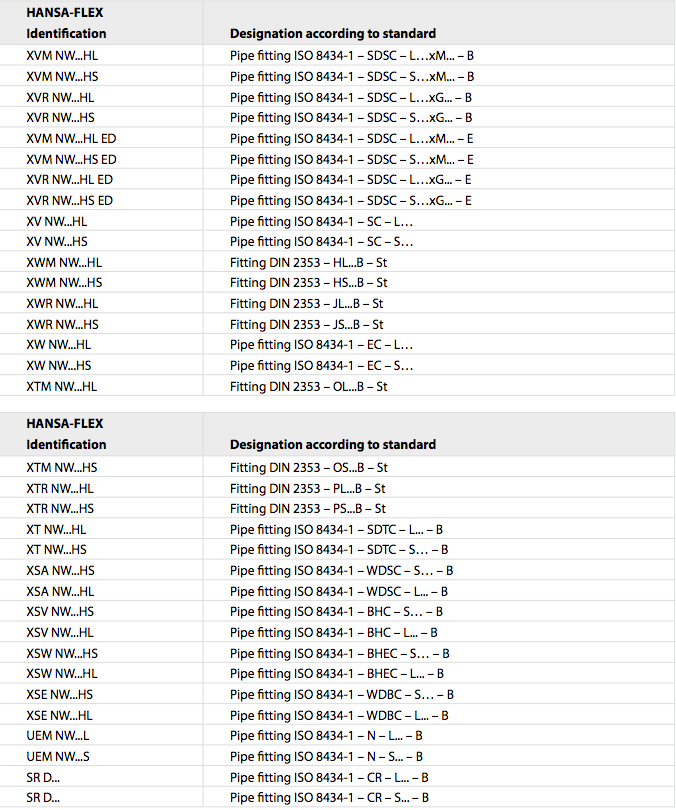
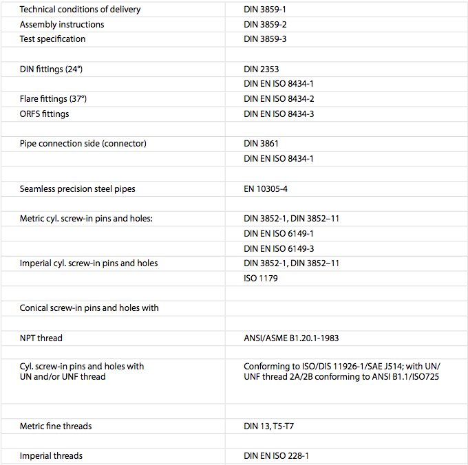
Applicable standards for pipe ttings:
8. Operating Temperatures of 24°-cutting ring fittings

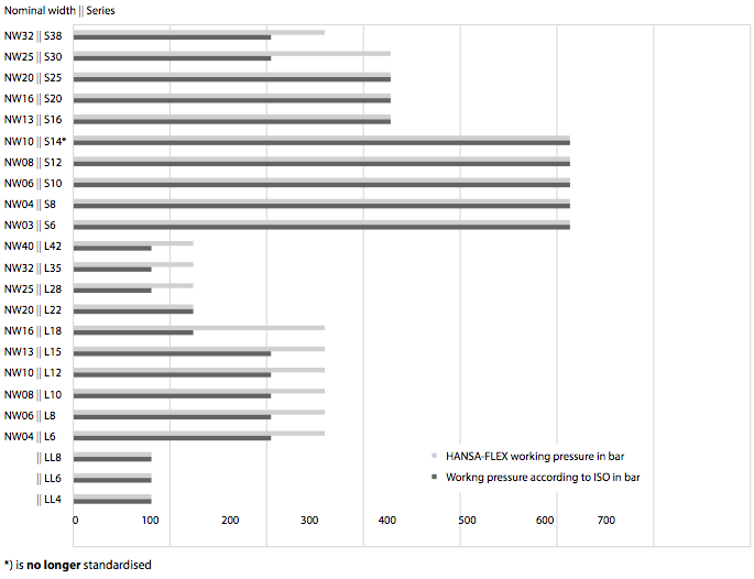
9. Operating pressure of 24°- cutting ring fittings
The HANSA-FLEX range of fittings is divided into three series according to pressure level and application:
LL: very light series
L : light series
S : heavy duty series
Information about ttings often includes the nominal pressure, designated PN. The nominal pressure, PN, is merely an index that serves as an identi er or designator for a part or system. The PN designation is used internationally.
With this indication of the PN nominal pressure, HANSA-FLEX cutting ring ttings o er a quad-ruple safety factor. Flare ttings conforming to ISO 8434-2 also have a safety factor of 4.
It should be noted that this safety factor is contingent on error-free assembly and correct routing of the pipeline system.
However, HANSA-FLEX cutting ring ttings are designed in such a way that the pressure values required according to DIN EN ISO 8434-1 are exceeded. The pressure ranges indicated are based on the connector shape. The various screw-in shapes should be noted, deviations may occur under certain circumstances.
Please direct enquiries to the Application Technology department.
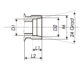
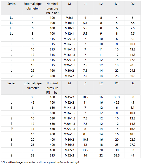
10. Pipe-side connection of cutting ring fittings
The pipe-side connection of HANSA-FLEX cutting ring fittings is standardised according to DIN 3861, hole shape W and DIN EN ISO 8434-1, and it is thus guaranteed that it can also be replaced with metric fittings for hydraulic hose lines:
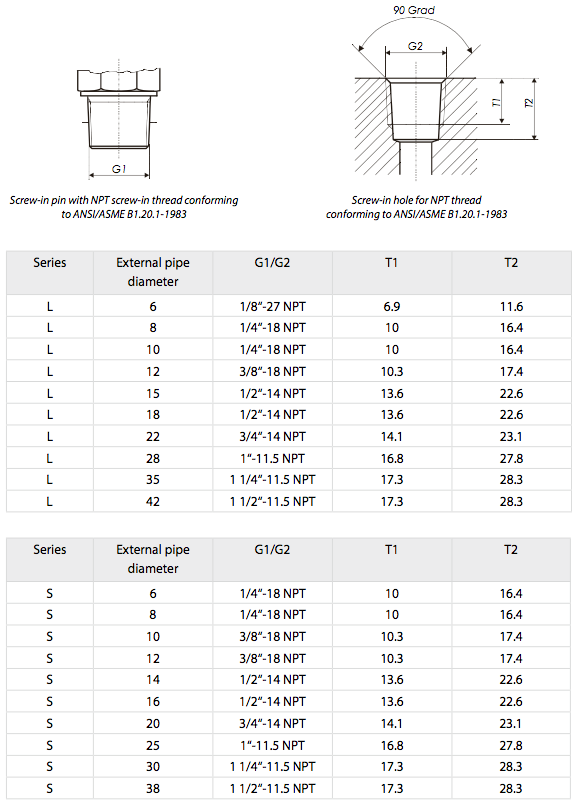
11. Screw-in pins and holes for HANSA-FLEX cutting ring fittings
HANSA-FLEX cutting ring ttings are available with a wide range of standardised screw-in threads, enabling them to be used for an enormous variety of applications.
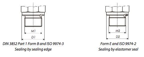
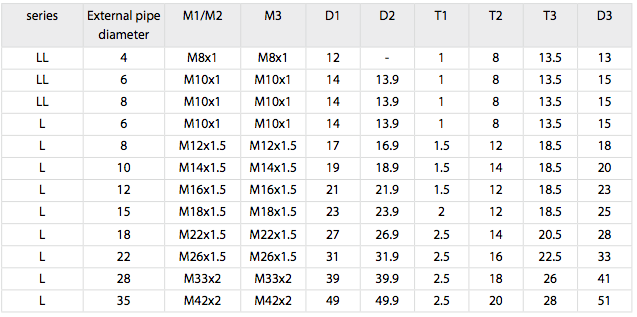
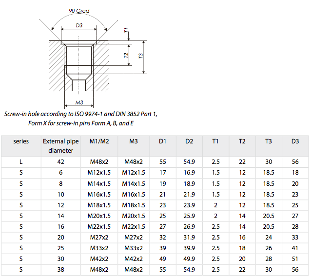
a) Metric screw-in pins according to DIN 3852 Part 1, Form B, and DIN 9974-2 Form E with the associated screw-in hole form X
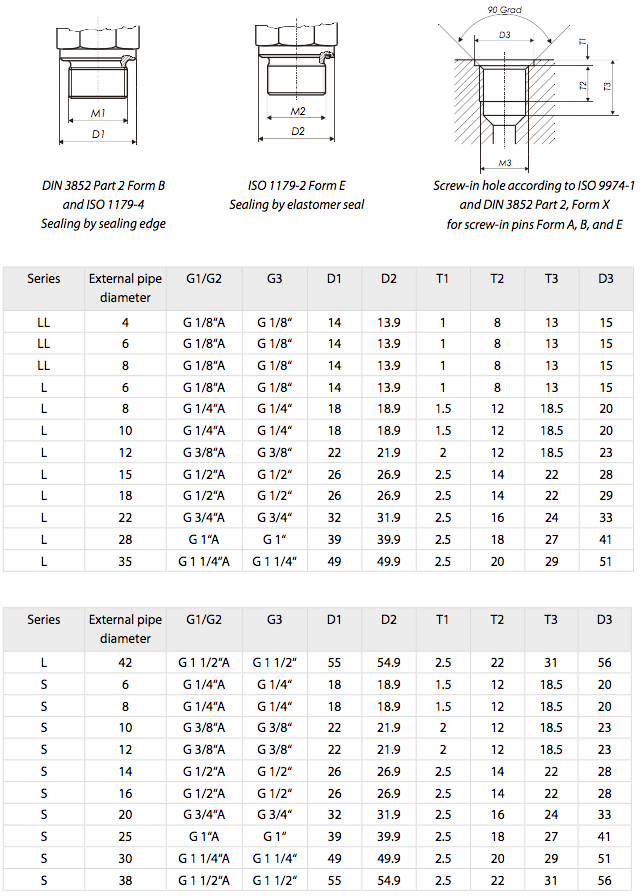
b) Imperial screw-in pins and holes according to DIN 3852 Part 2, Form B, and DIN 1179-2 Form E with the associated screw-in hole form X
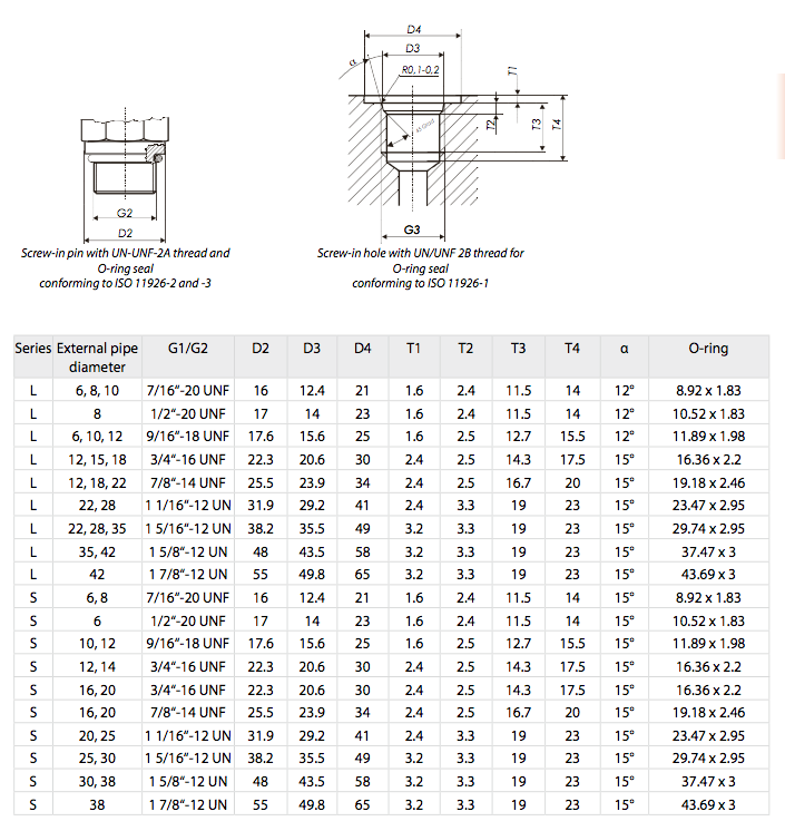
c) Screw-in pins and holes for pipe fittings with cylindrical US threaded connections conforming to ISO 11926-2/3
d) Screw-in pins and holes for pipe fittings with NPT thread conforming to ANSI/ASME B1.20.1-1983
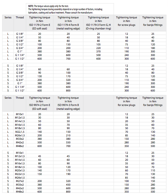
12. Tightening torques for screw-in pins in HANSA-FLEX cutting ring fittings
The following list of tightening torques applies for steel fittings with zinc-nickel coated screw-in pins for locking screws and banjo couplings, all with HANSA-FLEX CrVI-free surface and a mating part manufactured from the same material.
Tightening torques for stainless steel fittings and for fittings with UN/UNF threads available upon request.
In order to achieve an optimum seal, conical screw-in threads must be provided with an additional sealing means, e.g., Teflon tape.
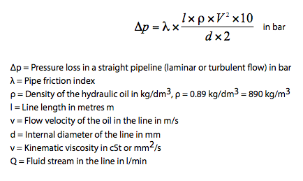
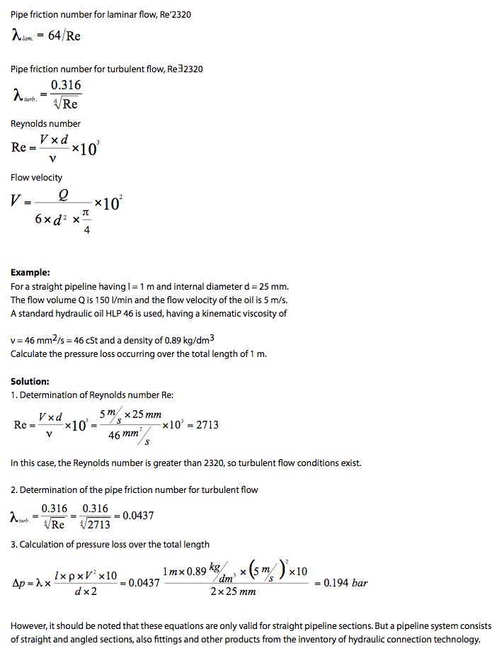
13. Determination of pressure loss in pipelines
The pressure losses that inevitably occur in pipeline systems can be recorded either by measuring equipment or by calculation.
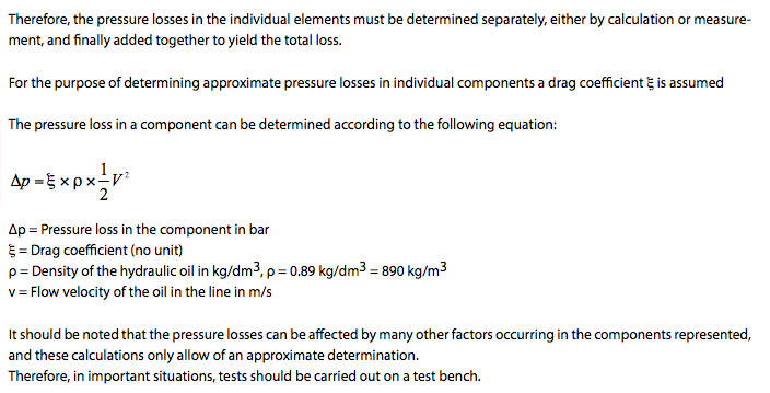
Determination of these losses precisely by calculation is associated with considerable effort, but at this point we are reproducing a few simple equations that can be used to determine approximate pressure losses in straight pipelines and fittings.
The pressure losses and ow resistance in a line system are dependent on the internal diameter of the pipe, the ow velocity and the properties of the hydraulic oil (density and viscosity).
Pressure losses are caused by “fluid friction”, i.e., the friction between the oil and the pipe walls, and the internal friction within the fluid.
Above a certain velocity, the laminar ow of the oil becomes a turbulent ow. Turbulent flows lead to greater heat generation in the system, with consequential losses of pressure and performance.
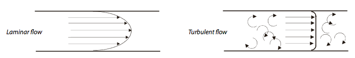
The behaviour of the ow is also characterised by the Reynolds number Re.
If this Re number exceeds a given value, the laminar oil ow becomes a turbulent flow.
In pipelines, laminar flow is most desirable. Turbulent flow occurs most often in valves, couplings and ball valves. The pressure losses in straight pipelines can be determined approximately with the aid of the following equations:
Assembly instructions, cutting ring/compression fitting
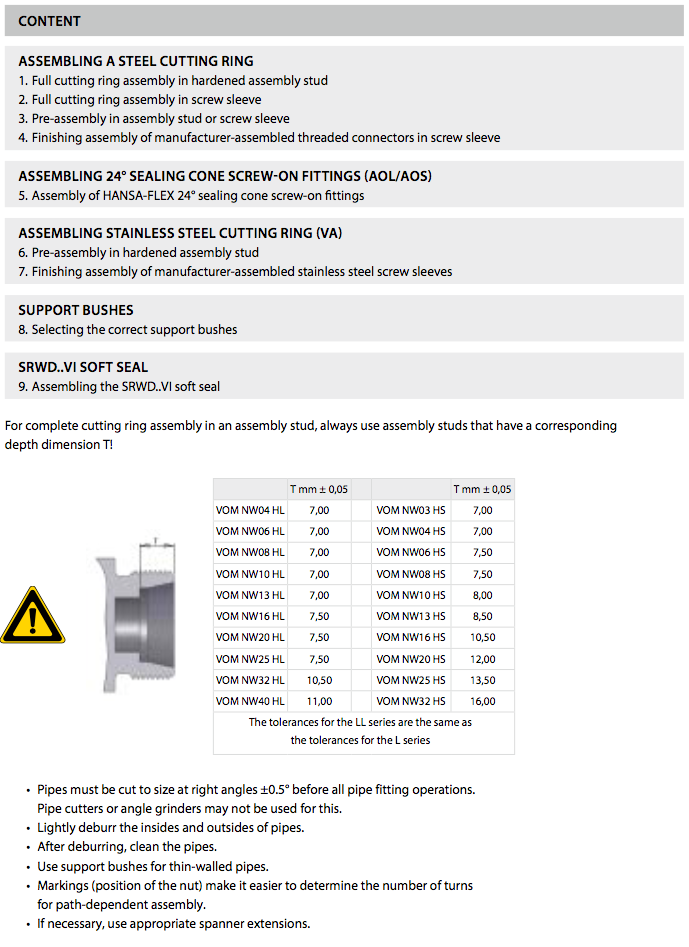
1. Full cutting ring assembly in hardened assembly stud (VONMNW)
Introduction
This instruction describes the complete assembly of a cutting ring (SRD) on the pipe in an assembly stud (VOMNW...). This is not pre-assembly!
Preparation
Lightly lubricate the thread and cone of the assembly stud and the thread of the union nut.
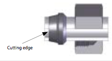
Slide the union nut and cutting ring onto the pipe, making sure that the cutting ring is in the correct position; the cutting edges of the cutting ring must face towards the end of the pipe, otherwise assembly will be incorrect.
Cutting ring assembly
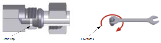
- Tighten the union nut until the force required to turn it* increases noticeably; at the same time, push the pipe firmly against the limit stop in the assembly stud, otherwise the pipe will not be cut properly. The pipe must not be allowed to turn during assembly.
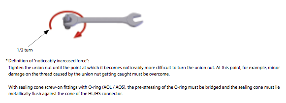
- Tighten union nut 11⁄2 turns with a spanner.
Inspection
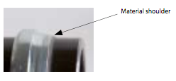
Disassemble the pipe or threaded connection and check that a clearly visible shoulder of cut material is present in front of the first (front) cutting edge. At this point, the cutting ring may be allowed to rotate, but must not move axially.
Re-assembly
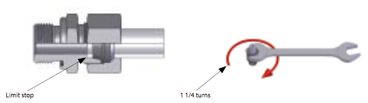
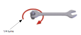
Oil the threads of the union nut and the screw sleeve. Thread the union nut onto the screw fitting until the force required to turn it* increases noticeably. Turn the union nut of the threaded connection or pipe not more than 1/4 turn further with the spanner (tighten / tighten fully).
The cones of the assembly studs are subject to normal wear and must be checked at regular intervals with taper gauges.
Definition of “noticeably increased force”:
Tighten the union nut until the point at which it becomes noticeably more di cult to turn the union nut. At this point, for example, minor damage on the thread caused by the union nut getting caught must be overcome.
With sealing cone screw-on fittings with O-ring (AOL / AOS), the pre-stressing of the O-ring must be bridged and the sealing cone must lie metallically flush against the cone of the HL/HS connector.
2. Full cutting ring assembly in screw sleeve
Introduction
This instruction describes the complete assembly of a cutting ring (SRD) on the pipe in a screw sleeve. This is not pre-assembly!
Preperation
- Lightly oil the cone of the screw sleeve and the thread of the union nut.
- Slide the union nut and cutting ring onto the pipe, making sure that the cutting ring is in the correct position; the cutting edges of the cutting ring must face towards the end of the pipe, otherwise assembly will be incorrect.
Cutting ring assembly
- Tighten the union nut until the force required to turn it* increases noticeably; at the same time, push the pipe firmly against the limit stop in the assembly stud, otherwise the pipe will not be cut properly. The pipe must not be allowed to turn during assembly.
- Tighten union nut 11⁄2 turns with a spanner. Brace the screw sleeve with a spanner.
Inspection
Disassemble the pipe or threaded connection and check that a clearly visible shoulder of cut material is present in front of the first (front) cutting edge. At this point, the cutting ring may be allowed to rotate, but must not move axially.
Re-assembly
Oil the threads of the union nut and the screw sleeve. Thread the union nut onto the screw fitting until the force required to turn it* increases noticeably. Turn the union nut of the threaded connection or pipe not more than 1/4 turn further with the spanner (tighten / tighten fully).
The cones of the assembly studs are subject to normal wear and must be checked at regular intervals with taper gauges.
Definition of “noticeably increased force”:
Tighten the union nut until the point at which it becomes noticeably more di cult to turn the union nut. At this point, for example, minor damage on the thread caused by the union nut getting caught must be overcome.
With sealing cone screw-on fittings with O-ring (AOL / AOS), the pre-stressing of the O-ring must be bridged and the sealing cone must lie metallically flush against the cone of the HL/HS connector.
3. Pre-assembly in assembly stud or screw sleeve
Introduction
This instruction describes the pre-assembly of a cutting ring (SRD) on the pipe in a pipe screw sleeve or assembly stud.
Preperation
- Lightly oil the cone of the screw sleeve and the thread of the union nut.
- Slide the union nut and cutting ring onto the pipe, making sure that the cutting ring is in the correct position; the cutting edges of the cutting ring must face towards the end of the pipe, otherwise assembly will be incorrect.
Cutting ring assembly
- Tighten the union nut until the force required to turn it* increases noticeably; at the same time, push the pipe firmly against the limit stop in the screw sleeve, otherwise the pipe will not be cut properly. The pipe must not be allowed to turn during assembly.
- Tighten union nut 1/4 turn with a spanner. Brace the screw sleeve with a spanner.
Inspection
Disassemble the pipe and check that a clearly visible shoulder of cut material is present in front of the rst (front) cutting edge. In this case, the cutting ring may be allowed to rotate, but must not move axially.
*Definition of “noticeably increased force”:
Tighten the union nut until the point at which it becomes noticeably more di cult to turn the union nut. At this point, for example, minor damage on the thread caused by the union nut getting caught must be overcome.
With sealing cone screw-on ttings with O-ring (AOL / AOS), the pre-stressing of the O-ring must be bridged and the sealing cone must lie metallically ush against the cone of the HL/HS connector.
4. Finishing assembly of manufacturer-asembled threaded connectors in screw sleeve
- In these threaded connections, the cutting ring has been pre-assembled by the manufacturer.
- Check that the cutting ring is positioned and seated correctly, and that the shoulder of cut material is present.
- Oil the thread of the union nut, the cutting ring and the screw sleeve thread.
- Tighten the union nut until the force required to turn it increases noticeably*.
- Tighten union nut 1/4 turns, bracing the screw sleeve with a spanner.
We recommend switching to HANSA-FLEX 24° sealing cone screw-on fittings.
5. Assembling 24° Sealing cone screw-on fittings (AOL/AOS)
- Lightly oil the cone of the screw sleeve and the thread of the union nut. Place screw tting (sealing cone) evenly on the theaded connection.
- Thread the union nut of the sealing cone screw-on fitting onto the screw fitting until the force
- required to turn it* increases noticeably.
- Turn the union nut of the sealing cone screw-on fitting or pipe not more than 1/4 turn further
- with the spanner (tighten / tighten fully).
* Definition of “noticeably increased force”:
Tighten the union nut until the point at which it becomes noticeably more di cult to turn the union nut. At this point, for example, minor damage on the thread caused by the union nut getting caught must be overcome.
With sealing cone screw-on ttings with O-ring (AOL / AOS), the pre-stressing of the O-ring must be bridged and the sealing cone must lie metallically ush against the cone of the HL/HS connector.
6. Assembly in hardened assembly stud (VOMNW...) Stainless steel
Introduction
This instruction describes the pre-assembly of a cutting ring (SRD...VA) on the stainless steel pipe in the assembly stud and the finishing assembly of the cutting ring in the screw sleeve.
Preperation
- Grease the thread and cone of the assembly stud and the thread of the union nut with HANSA-FLEX fitting grease.
- Slide the union nut and cutting ring onto the pipe, making sure that the cutting ring is in the correct position; the cutting edges of the cutting ring must face towards the end of the pipe, otherwise assembly will be incorrect.
Cutting ring assembly
- Tighten the union nut until the force required to turn it* increases noticeably; at the same time, push the pipe firmly against the limit stop in the assembly stud, otherwise the pipe will not be cut properly.
- Tighten union nut 1/4 turn with a spanner.
Inspection
- Disassemble the pipe or threaded connection and check that a clearly visible shoulder of cut material is present in front of the first (front) cutting edge. In this case, the cutting ring may be allowed to rotate, but must not move axially.
Finishing assembly
- Grease the threads of the union nut and the screw sleeve with HANSA-FLEX assembly grease. Thread the union nut onto the screw fitting until the force required to turn it* increases noticeably. Continue turning union nut about 1/2 turn with the spanner.
Re-assembly
Grease the threads of the union nut and the screw sleeve with HANSA-FLEX assembly grease. Thread the union nut onto the screw tting until the force required to turn it* increases noticeably. Turn the union nut of the threaded connection or pipe about 1/4 of a turn further with the spanner (tighten / tighten fully).
The cones of the assembly studs are subject to normal wear and must be checked at regular intervals with taper gauges. Each screw sleeve must be used only once for finishing assembly on the pipe; using the same sleeve again may impair its function.
It is not permitted to carry out pre-assembly in the screw sleeve!
* Definition of “noticeably increased force”:
Tighten the union nut until the point at which it becomes noticeably more di cult to turn the union nut. At this point, for example, minor damage on the thread caused by the union nut getting caught must be overcome.
With sealing cone screw-on fittings with O-ring (AOL / AOS), the pre-stressing of the O-ring must be bridged and the sealing cone must lie metallically flush against the cone of the HL/HS connector.
7. Finishing assembly of manufacturer-assembled stainless steel threaded connectors in screw sleeve
- In these threaded connections, the cutting ring has been pre-assembled by the manufacturer.
- Check that the cutting ring is positioned and seated correctly, and that the shoulder of cut material is present.
- Grease the thread of the union nut, the cutting ring and the thread of the screw sleeve with HANSA-FLEX assembly grease.
- Tighten the union nut until the force required to turn it increases noticeably*.
- Tighten union nut about 1/2 turn, bracing the screw sleeve with a spanner.
We recommend switching to HANSA-FLEX sealing cone screw-on fittings.
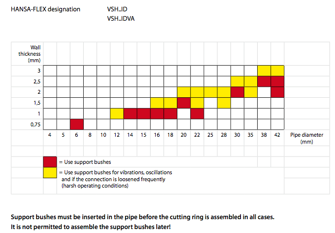
8. Correct selection of support bushes for thin-walled pipes made from steel and stainless steel
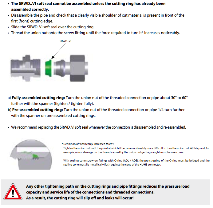
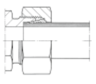
9. Assembling the SRWD..VI soft seal