Technical Information
Seals and Sealing Equipment
1. Installation instructions
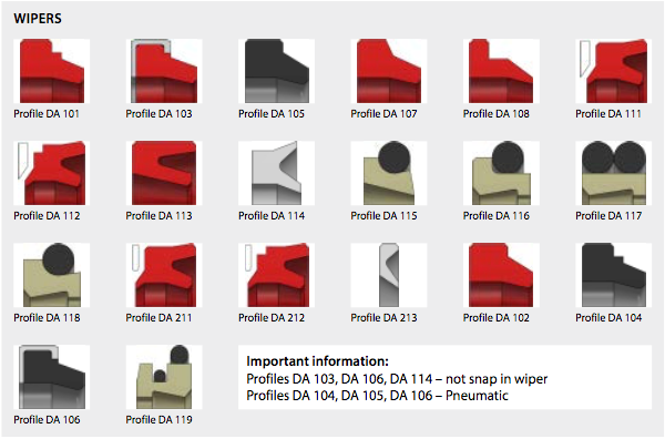
1.1 ROD SEALS AND WIPERS
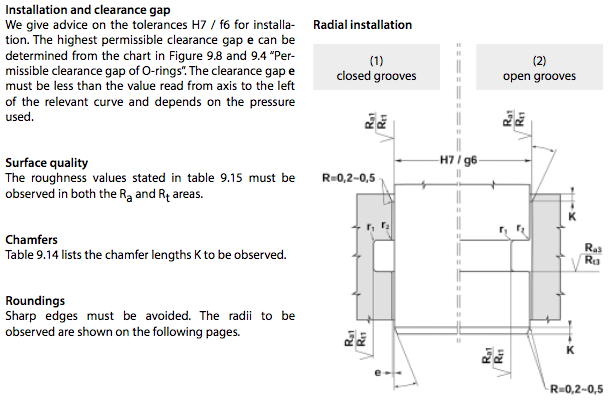
Surface quality
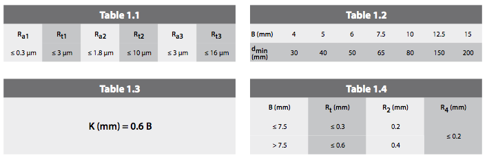
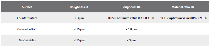
The roughness values stated in table 1.1 must be observed in both the Ra and Rt areas.
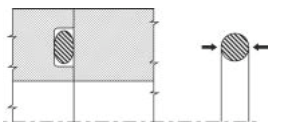
Open or closed grooves
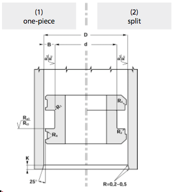
Table 1.2 can be used to establish whether a seal can be fitted in closed grooves (1). In the case of a specific cross-section B, we recommend fitting in open grooves (2) if the diameter of the rod is less than the minimum diameter (dmin).
Chamfers
Table 1.3 lists the chamfer lengths K to be observed.
Roundings
Sharp edges must be avoided. Table 1.4 lists the radii to be observed.
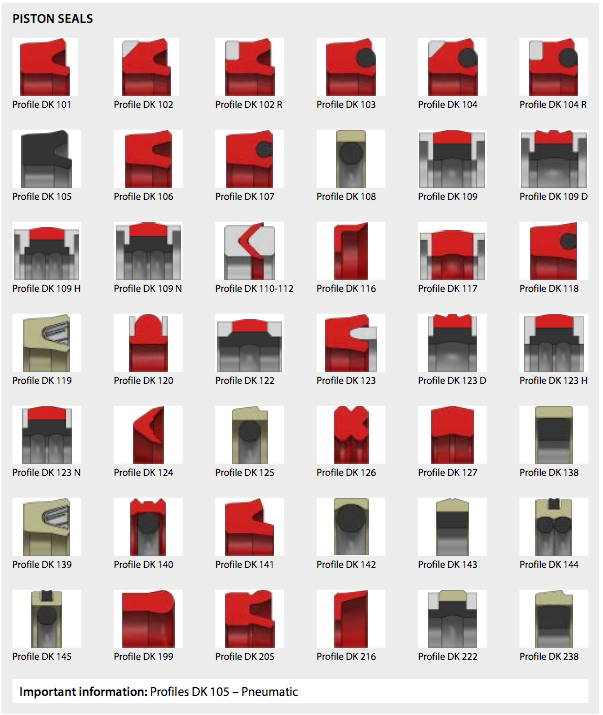
1.2 PISTON SEALS AND GUIDE RINGS
Surface quality
The roughness values stated in table 1.1 must be observed in both the Ra and Rt areas.
Single or multipart pistons
Please refer to the “Installation” instructions in this cat- alogue for each seal profile and each individual seal.
Chamfers
Table 1.3 lists the chamfer lengths K to be observed.
Roundings
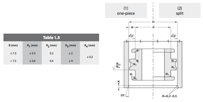
Sharp edges must be avoided. Table 1.5 lists the radii to be observed.
1.3 STATIC SEALS – RADIAL INSTALLATION

The static seal is squeezed between its external and internal diameters.
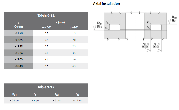
1.4 STATIC SEALS – AXIAL INSTALLATION
The static seal is squeezed between its two side faces.
2. Correct Installation
Hydraulic seals can be damaged if they are not correctly installed. This can result in many problems, which can be avoided by observing the following guidelines:
- Check that the groove diameters, tolerances, surface qualities and chamfers are based on the val- ues given in this catalogue.
- Ensure that the seal does not come in contact with sharp edges, bored holes or threads during assembly.
- All metal parts must be absolutely clean and free of swarf, weld splatter and defects.
- All seals must be lubricated before assembly with the same liquid or a liquid compatible with that which will be used in the hydraulic system.
- Do not use sharp-edged tools for installation. Do not allow seals to be deformed for a prolonged period during installation.
- Ensure the seal is correctly oriented with respect to the direction of fluid pressure. The same applies to all the other parts.
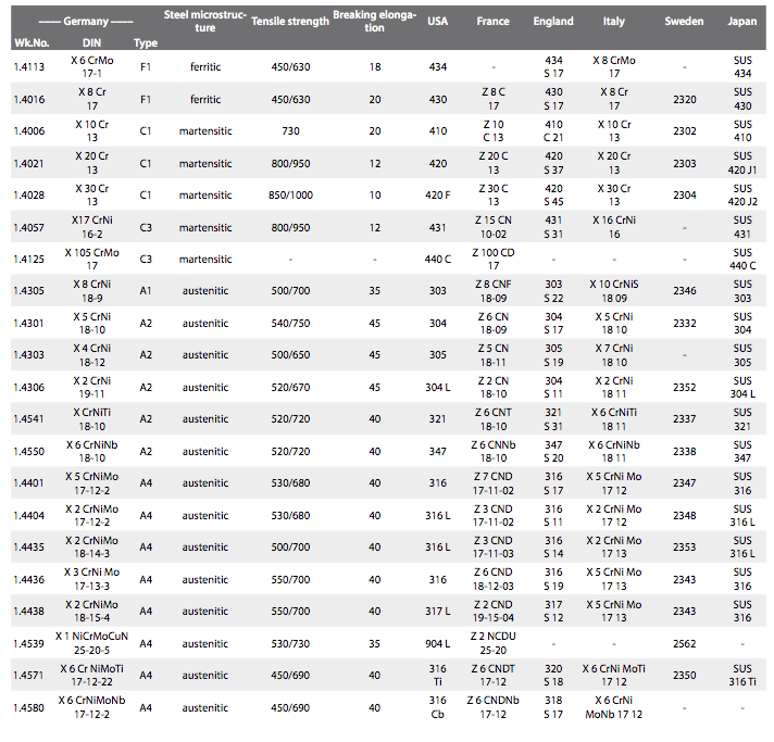
3. Table of international steel grades and their equivalents
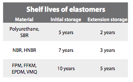
4. Storage conditions for elastomers
- Max. 25 °C
- Keep away from direct sources of heat
- Keep out of direct sunlight
- Install low-UV lighting
- Max. air humidity 60 % prevent condensation occurring
- Keep away from ionizing radiation and the effects of ozone,
- for example produced by welding work
- Store in a PE bag or the original packaging
- Do not store hung up on a hook or similar
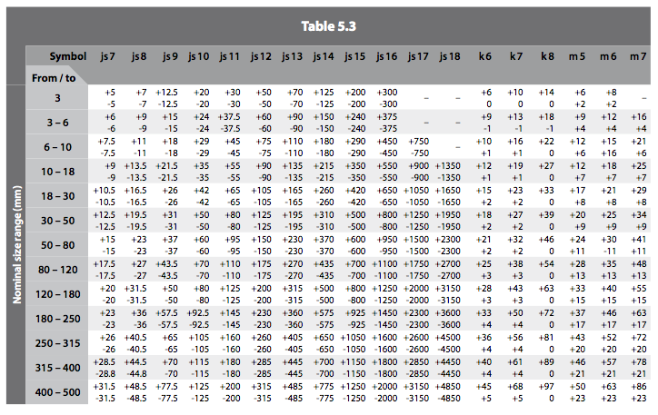
5. Tolerances and fits
Table of ISO tolerances basic hole / basic shaft in accordance with ISO 286.
The allowances for shafts are given in accordance with DIN 7160; for holes the standard is DIN 7161.
ALLOWANCES FOR HOLES AND SHAFTS
The ISO system for tolerances and fits relate to all linear parameters such as external dimensions, internal dimen- sions, diameters, lengths, widths, heights and thicknesses.
A reference temperature 20 °C applies to all the dimensions defined in this system. Tables 5.1, 5.2 and 5.3 contain a selection of tolerances that are used successfully in the field of tool and mould making, and are the preferred values in HASCO standards. These tolerances are used in our technical documents to precisely describe our prod- ucts. These tolerances can also be used to advantage in other areas.
TOLERANCES FOR INTERNAL DIMENSIONS (HOLES)
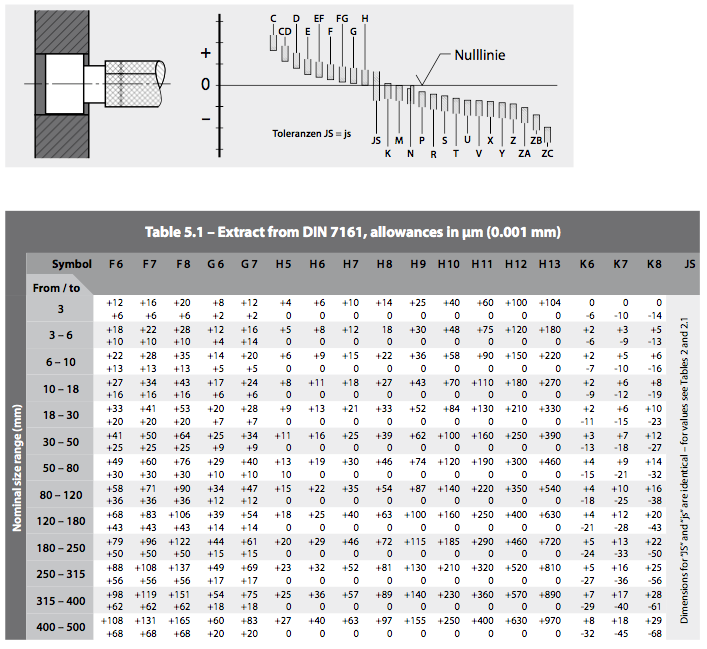
TOLERANCES FOR EXTERNAL DIMENSIONS (SHAFTS)

6. Surface quality parameters for seal housings
General requirements for seal housings.
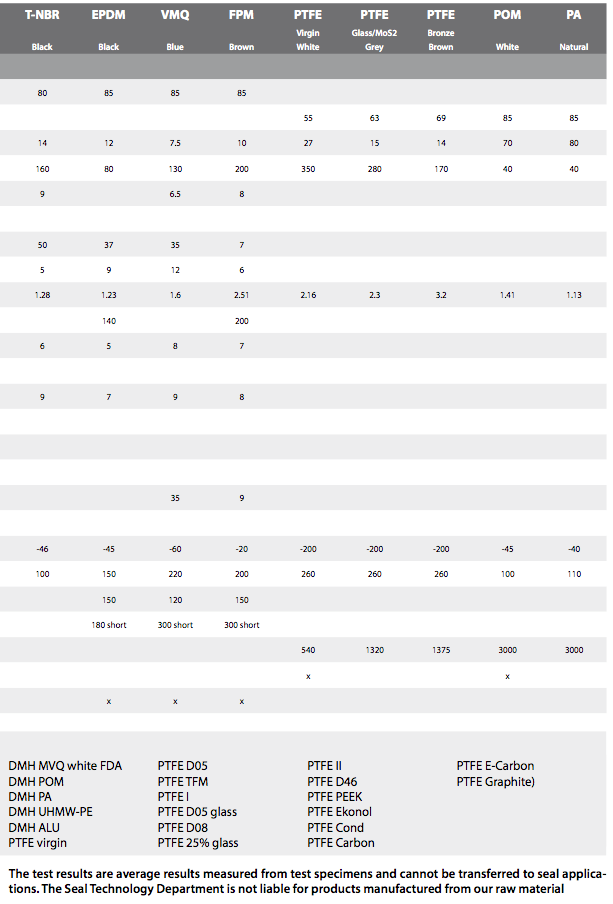
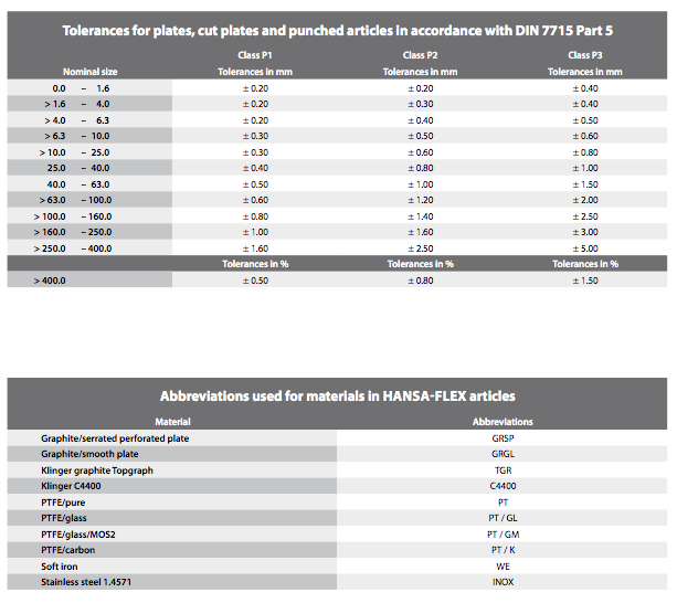
7. Abbreviations used for materials in HF seals

8. Bushes
8.1 General
Technical data
To make things clearer, we would like to define in advance some important technical data used repeat- edly in this document. For this purpose, we shall con- sider a bush with an internal diameter “d” and a width “L”.

Calculation of the service life
The service life of a bush depends on the specific bear- ing load, sliding speed, operating temperature and the shaft material (surface quality and hardness). On request, we can calculate a service life for you, but this can be no more than a guide.
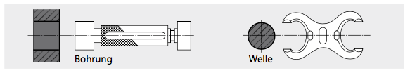
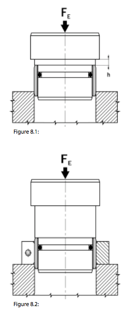
Installing the bushes
Use the basic arrangement shown in Figure 8.1 to install bushes with an external diameter of up to 50 mm. By machining the bearing surface at a specific height h, the bush can be pressed an exact depth h into the hole.
Use an auxiliary ring as shown in Figure 8.2 to fit bushes with an external diameter greater than 50 mm. On request, we can calculate the press-in force FE for you.
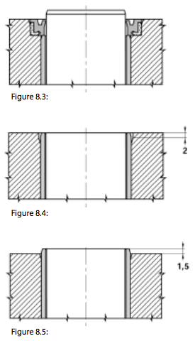
Installation principle
We recommend protecting the bushes against dirt by using type SWP seal ends or shaft seal rings (Fig. 8.3). Finally, chamfers should preferably be machined in order to prevent stress concentrations at the edges of the bushes (Fig. 8.4), or the bushes should project above the surrounding material (Fig. 8.5).
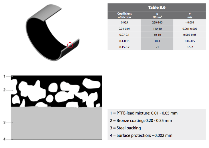
8.2 Maintenance-free bushes type BK-1
Construction
The BK-1 bush consists of a porous bronze coating (2) sinter-fused onto a steel backing (3). A PTFE-lead mixture (1) is then rolled into the bronze coating. The steel backing is protected against corrosion by external tin- or cop- per-plating (4).
Properties
The BK-1 bush has many advantages:
- Suitable for dry running and maintenance-free • Noise and frequency absorption
- Hydrodynamic operation possible
- High permissible load
- Good chemical resistance
- Good friction characteristics
- No stick-slip
- Wide temperature range
- High slide speed
- No water absorption
- Low play during operation
- Extremely space-saving
Areas of application
BK-1 bushes are suitable for translatory, rotary and oscillatory motions.
Application examples:
- Rod guide for pneumatic and hydraulic cylinders
- Attachment eyes for pneumatic and hydraulic cylinders
- Conveyor-belt systems, textile machinery, automobiles ...
8.3 Maintenance-free bushes type BK-2
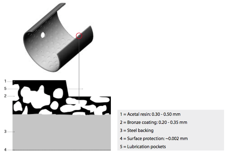
Construction
The BK-2 bush consists of a porous bronze coating (2) sinter-fused onto a steel backing (3). An acetal resin POM (1) is then rolled into the bronze coating. The steel backing is protected against corrosion by external tin- or cop- per-plating (4). Finally the lubrication pockets (5) are stamped into the slide coating.
Properties
The BK-2 bush has many advantages:
- Maintenance-free operation
- Noise and frequency absorption
- Relubricatable
- Hydrodynamic operation possible
- High permissible load
- Good friction characteristics
- High slide speed
- No water absorption
- Can be used where oil film formation is difficult • Low play during operation
- Extremely space-saving
Areas of application
BK-2 bushes are suitable for rotary and oscillatory motions. Initial lubrication with grease is advisable, and con- tinual lubrication substantially lengthens the service life of the slide bearing.
Application examples:
Attachment eyes for pneumatic and hydraulic cylinders Agricultural equipment
Material handling equipment
Construction machinery, ...
8.4 Bronze bushes type BK090
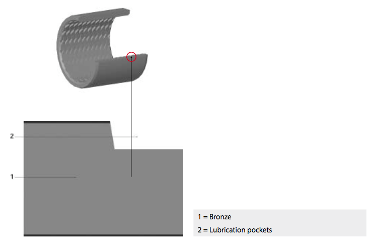
Construction
The BK090 bush is made entirely out of CuSn8 bronze and manufactured from calibrated rolled strips. The entire sliding surface is covered with diamond-shaped lubrication pockets. Lubricant is introduced into these pockets, which then function as reservoirs, releasing the lubricant progressively during operation. Drill holes to allow relubrication.
Properties
The BK090 bush has many advantages:
- Maintenance-free operation
- Relubricatable
- Suitable for dirty conditions
- Shock and vibration resistant
- High permissible load
- Good friction characteristics
- No water absorption
- Low play during operation
- Extremely space-saving
Areas of application
BK090 bushes are suitable for rotary and oscillatory motions. Initial lubrication with grease is advisable, and con- tinual lubrication substantially lengthens the service life of the slide bearing.
Application examples:
- Attachment eyes for hydraulic cylinders • Forestry machinery
- Agricultural equipment
- Conveyors and elevators
- Construction machinery, ...
9. O-Rings
9.1 DESCRIPTION OF O-RINGS
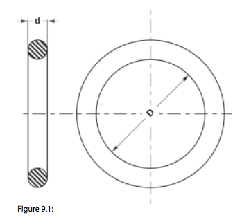
O-rings are ring-shaped seals with a round cross-sec- tion (a torus) defined by the inside diameter (D) and the cross-sectional diameter (d). It is the most com- mon seal type for hydraulic and pneumatic applications.
O-rings have the following advantages:
- The groove is simple and easy to machine
- Large choice of compounds: NBR, FPM, EPDM, silicone, PTFE, PUR, ...
- Easy to install due to its symmetry
- Attractive price thanks to new production techniques
- Extremely wide variety of applications: static, dynamic (both linear and rotary), ...
- Compact design
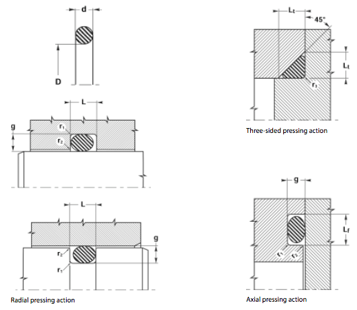
9.2 PRINCIPLE OF O-RINGS
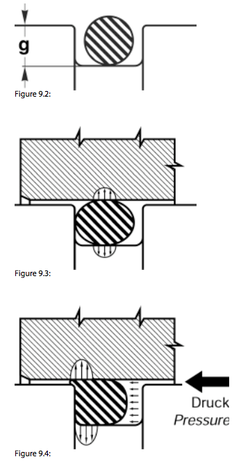
The functional principle is summarised in Figure 9.2:
- The O-ring is installed in a groove with a depth g smaller than the diameter d of the cross-section (Fig. 9.2).
- After installation, the O-ring seal is squeezed
and this creates a pressing action (Fig. 9.3). - The media exerts pressure on the O-ring and intensifies the initial pressing action (Fig. 9.4).
The initial precompression (Fig. 9.3) is very important! Depending on the application and material, the com- pression of the elastomer will change as follows:
- From 3 to 20 % dynamic seal (pneumatic and hydraulic). In this catalogue, the initial pressure fluctuates between 12 and 14 % for a dynamic seal
- From 15 to 30 % static seal. In this catalogue, the initial pressure used for a static seal fluctu- ates between 17 and 27 %.
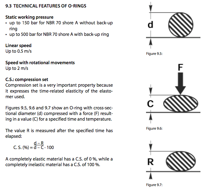
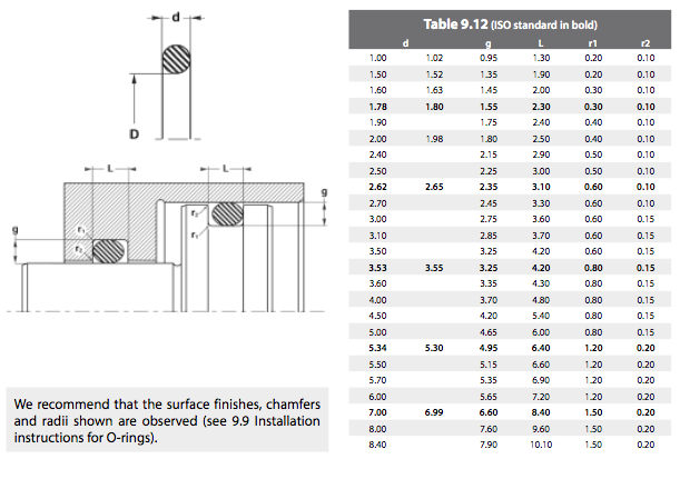
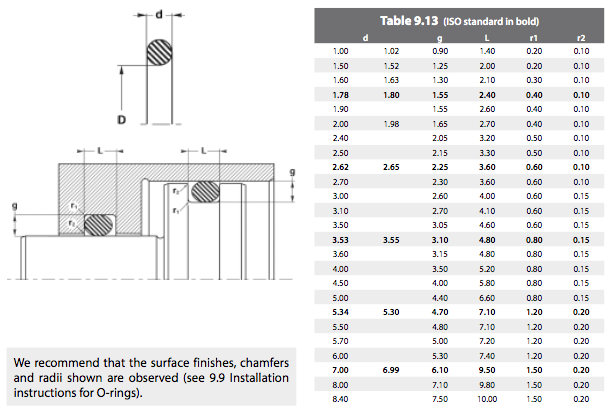
9.3 TECHNICAL FEATURES OF O-RINGS
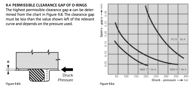
9.4 Permissibile clearance gap of o-rings
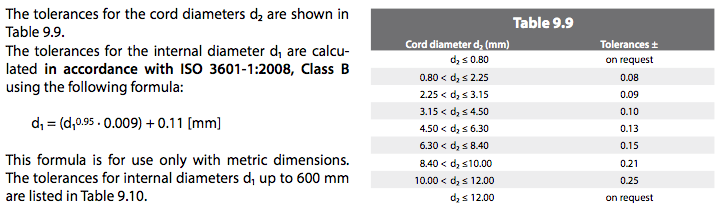
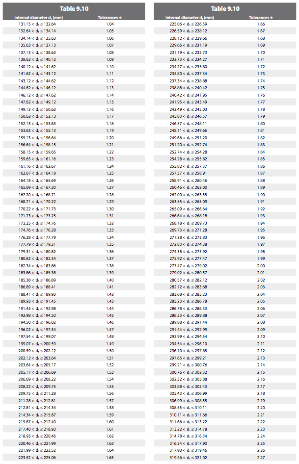
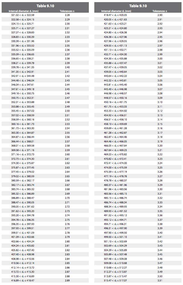
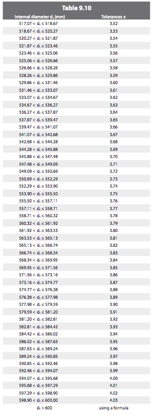
9.5 DIMENSIONAL TOLERANCES FOR O-RINGS IN ACCORDANCE WITH ISO 3601-1:2008 CLASS B

9.6 STATIC SEAL OF O-RINGS

9.7 DYNAMIC SEAL FOR PNEUMATIC CYLINDERS
9.8 DYNAMIC SEAL FOR HYDRAULIC CYLINDERS
9.9 INSTALLATION INSTRUCTIONS FOR O-RINGS
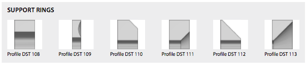
10. Back-up rings
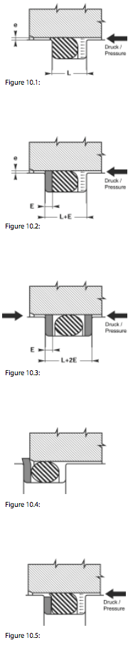
10.1 EXTRUSION
Extrusion problems occur when the clearance gap e between the parts in relation to the pressure deforming the O-ring is too large. The O-ring becomes gradually worn at the edges and wears out completely over time (Fig. 10.1).
The groove is widened by the value E (thickness of the back-up ring). This back-up ring is installed on the side facing the direction of pressure. This sup- ports the O-ring and solves extrusion problems (Fig. 10.2).
Back-up rings are used similarly for double-acting sealing systems. In this case, two back-up rings are required (Fig. 10.3).
10.2 PROFILES AND MATERIALS
We recommend solid back-up rings for internal and external grooves. PTFE must be used in applications with high temperatures and special fluids. For external grooves, the back-up rings have to be cut through to allow installation.
10.3 FURTHER INFORMATION
Although a back-up ring is a very simple product, its choice and dimensions can be very complex, as we will demonstrate below.
- A The problem of replacing existing parts: there is an enormous differ- ence in the depth of the grooves used. The initial compression can vary between 10 and 30 % (see page 228).
Example: our standard rings BU and PBK. For an O-ring d = 2.62 mm, the section of the ring will be 2.25 mm for the PBK and 2.18 mm for the BU. Therefore the determination of the dimensions of the existing pieces must be done very carefully, because any dimension is possible; every manufacturer uses different standards.
Incorrectly determined dimensions can have disastrous consequences. If the ring is a poor fit for the groove, it can cause the following problems:- If the cross-section of the ring is too large, installation will be difficult,
if not impossible and the ring will inevitably wear out (see Fig. 10.4). - On the other hand, if the cross-section is too small, there is no point in installing it: the extrusion problem is as bad as ever, as can be seen
in Figure 10.5.
- If the cross-section of the ring is too large, installation will be difficult,
- B With respect to the new versions, the seal manufacturers’ standard ranges are very often limited. The same ring is used for static and dynamic sealing.
Example: our PBK rings are often used for static sealing. However, they are more suitable for dynamic applications (see Table 9.13 in “9.8 Dynamic seal for hydraulic cylinders”). PBK rings are used in static appli- cations mainly on the grounds of economy. However this conflicts with the groove depth we recommend in “9.9 Installation instructions for O-rings”. For dimensions corresponding to those in Table 9.14, we recom- mend a DST 108 in H-PU.
Selecting a back-up ring for a new design is completely different to selecting one as a replacement.
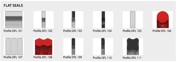
11. Flat seals
11.1 FLAT SEALS IN ACCORDANCE WITH EN1514-1 (DIN 2690, 2691, 2692)

11.2 DIMENSIONS AND TOLERANCES FOR SEALING PLATES, CUT PLATES AND PUNCHED ARTICLES
12. On-demand seal production
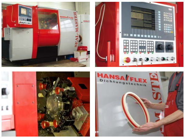
The HANSA-FLEX seal production centre
With two SEAL-MASTER CNC manufacturing facilities we are able to produce precision seals and special turned parts immediately in plastic or aluminium from 5 – 520 mm using computer-assisted manufacturing techniques. We store thousands of seals as datasets in the production centre’s computer ready for just-in-time manufacture of seals from 5 – 520 mm directly to order. We offer same-day supply of almost any seal, whether standard or special profile.
The advantages of seal production
All seals and special turned parts can be produced as custom parts or standard parts in a mass series or individu- ally with the highest level of precision. Our production software has over one hundred pre-programmed stand- ard profiles. Hence, we are capable of adapting to the specific needs of our customers.
Furthermore, we maintain a standard seal stock with over 11,000 different seal types and dimensions ready and waiting for our customers.
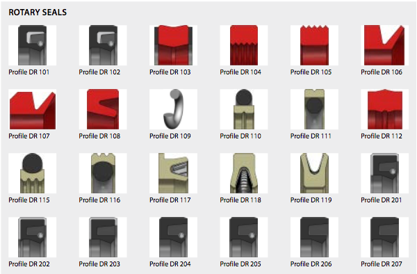
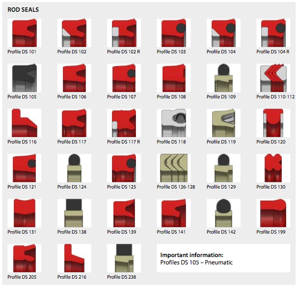
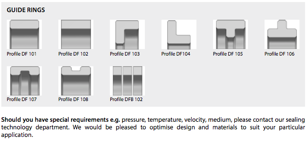
13. Seal profiles
14. Material datasheet